PassMark USB Power Delivery Tester PRO FAQ
Can I run multiple testers at the same time on one PC?
- Yes, you can control & monitor multiple testers from one PC. You'll need a USB port per unit. For each unit connected you need to run a separate instance of the software.
Is there a PD protocol analyzer in the PC software?
- Yes, the PC software can record and display all power delivery messages sent and read by the tester.
Can the unit dissipate 240W continuously?
- Continuous 240W power dissipation is possible. To be sure it will work, the tester needs to be in cool environment (e.g. 21C) and have good airflow across the unit. The unit will auto-shut down if the heat sink temperature reaches 75C, or the internal MOSFET junction temperature reaches 150C.
Which revision of the USB PD protocol is supported?
- The USB Power Delivery Tester PRO supports PD3.1 with extended functionality to support features added in newer revisions of the USB Power Delivery protocol. This includes the Extended Power Range to support profiles up 48V and 5A, as well as SPR AVS type profiles added in USB PD 3.2.
Does the tester support Programmable Power Supply (PPS)?
- Programmable Power Supply (PPS) is one of additions to the USB-C Power Delivery 3.0 standard. A power supply’s output voltage can be programmatically adjusted in small increments (20mv) over its advertised range.
Does the tester support Quick Charge (QC)?
- Quick Charge is a Qualcomm’s proprietary technology which allows for the charging of battery powered devices at levels above and beyond the typical 5 volts and 2 amps. QC1, QC2, QC3, QC4 and QC4+ are all supported.
Is there a Linux driver for the device?
- Not at this time. But see the details about the API below. The device can also be used stand alone without any connection to a PC.
Is there an SDK / API to use the device from my own software?
- Yes. There is a protocol guide showing the commands required to control the to the device and example soure code (in C++ on Windows). See the USB PD Download page for details.
Does the device need to be connected to a PC?
- No. You can use the device in a standalone manner.
How many power profiles can be displayed / selected?
- A maximum of 20 profiles (depending on what the device under test supports)
Where can I get firmware updates?
- Firmware updates are available on the download page.
What voltages are supported?
- For the Sink port, any voltage between 3.3V to 48V can be used (depending on what power profiles the device under test supports). On the Source port, voltages between 3.3V to 20V can be provided.
What types of chargers can I emulate on the Source port?
-
The Source port is highly configurable allowing it to emulate most common chargers used for devices, as well as create uncommon chargers to test how the Device Under Test responds. The Source port supports the following protocols, each of which can be adjusted individually.
- USB Power Delivery (Up to 100W, Types: FIXED, PPS, SPR-AVS).
- Quick Charge 3 (200mV increments, 12V or 20V max).
- USB-C CC line pull-up resistor value, Rp (USB-C Default, USB-C @ 1.5A, USB-C @ 3A).
- BC1.2 SDP and DCP.
- All Apple / Divider Mode types.
- Samsung 2A / 1.2V/1.2V Mode.
Can I force an overcurrent situation?
- Yes, from the PC software you can override the limit advertised by the device. This can simulate a badly behaved / faulty USB device. This can be useful if you are an electrical engineer designing a charging device and need to test the safety of the USB charger. WARNING: While the expected behaviour of USB chargers is to shut down in an over current situation, this might not happen. The consequences of which might be a catastrophic failure of the device under test. Including smoke, fire, short circuits and electrocution hazards.
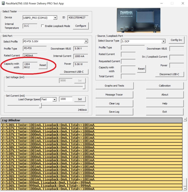
How can I measure the capacity of USB power banks?
-
To measure the capacity of a USB power bank or battery pack, first make sure that the battery is fully charged. With the USB Power Delivery Tester PRO switched on and connected to a monitoring machine with the monitoring software running, first click the "Reset Capacity" button in the user interface. Then, connect the power bank to the USB Power Delivery Tester PRO. Then, set the current to a value that fairly demonstrates the power bank's capabilities (e.g. 1000mA or 1500mA). The current can be set precisely using the USBPD Test software user interface. Note that it is not necessary to set the current to the maximum advertised current as higher currents can result in more heat dissipation which will reduce the efficiency of the power bank's output. Then, leave the device running until the voltage is zero. Note that this could take more than an hour. Once the voltage is zero, the powerbank has been fully depleted. Take note of value displayed under "Capacity". The value is given in mAh (milliamp hours). As an example, a capacity value of 2000mAh produced with a current of 1000mA would indicate that the powerbank delivered for a total of 2 hours, and a capacity value of 2250mAh produced with a current of 1500mA would indicate that the powerbank delivered for a total of 1.5 hours. Below is a screenshot of a measurement obtained after drawing 1000mA current from a powerbank for about 1.3 hours. The capacity reads 1304mAh.
Is calibration required?
- The unit should provide accurate measurements out of the box, with its default calibration. Typical default accuracy is around 1% for voltage readings and ±10mA for current measurement. So, for most uses, further calibration is not required. However, experienced users with suitable 3rd party equipment can calibrate the PM240 testers to improve the voltage and current measurement accuracy.
Can I test USB Type-C cables using the USB Power Delivery Tester PRO?
- Yes, using the USB Power Delivery Tester PRO in conjunction with a Passmark USB3 loopback plug, you can test USB Type-C cables to check the quoted current, voltage drop and data integrity over the cable.
-
Tools needed:
- A USB Power Delivery Tester PRO
- USB3 loopback plug
- A desktop computer with a USB Type-C port (PD support). The current rating of the Type-C port should be higher than the current capability of the cable being tested.
-
Set up the test environment
- Power up the USB Power Deliver Tester PRO by connecting the analysis port to the computer
- Attach a USB3 loopback plug to the loopback port of the USB Power Delivery Tester PRO
- Run the USBPDTest application
- Enable the loopback port from the menu
- Make sure Current Limit is set to "Enforce Limits"
- Run the USB30Test application
- Select loopback testing and enable the "Check Bus Error" option from the configuration window
-
How to test a cable
Test the Power Delivery communication
- Connect the USB host port to the "the Device Under Test" port using the USB Type-C cable that need to be tested. If the "Rotate Connector" message appeared on the tester's LCD, flip the cable from where it is attached to the "Device Under Test" port.
- Check the advertised profiles in the log window. You should be able to see all the port power profiles with the current level equal or less than the cable current rating.
-
Check the maximum voltage drop
- Find the voltage level that corresponds to the highest available current and select it from the "Voltage" drop down list
- Wait for "Port capability changed" message to appear in the log window. This means that the PD communication has been successful and the new profile is selected and provided by the port.
- Move the slider to the maximum current and check the voltage to make sure the voltage remains within the specification. If voltage goes outside the valid range, a log line with red color will appear.
-
Check data integrity
- On the USB30Test application, click on the "Start" button and monitor the log window to make sure the communication is error-free. The test should run at least for 10 seconds and at the end of the loopback test no error should be reported.
Can USB chargers/ports be tested in an automated fashion using the Passmark USB Power Delivery Tester PRO?
- Yes, we have an example Python script that does automated testing on a list of user selected profiles. The script selects the profiles one by one and performs voltage test across different loads and will prompt the user if voltage is outside the specification. It also gives an overall pass/fail at the end of the test.
Is the device suitable for high volume testing?
- The USB-C connector is small and fragile. This is the case for all devices with a USB-C connector. The connector is not designed for a high volume of cable insertions and removals such that might occur in a production line environment. Eventually the pins wear an start to make intermittent electrical contact. Twisting or too much insertion force on the connector can also result in it becoming loose and failing.
- If production line testing is required (e.g. 100s of insertions and removals per day) we suggest using an additional “disposable” extension cable that can remain permanently connected to the USB-PD tester. Once the connector on the disposable cable inevitably fails it can be replaced at low cost.
What are the best practices when using USB Type-C ports?
-
USB Type-C ports are made up of 24 small pins that are spaced 0.5mm apart from each other. This design makes the connector very fragile, as well as increasing the chance that two pins get shorted together. To avoid damaging the USB Type-C port, we recommend the following when attaching and detaching any device to the USB Power Delivery Tester.
- Insert and remove the cable as straight as possible.
- Never detach the cable when more than 5V is selected. A short between two pins is more likely in this case and can cause damage.
- Don’t insert the cable with more force than is required.
- Leave one side of the cable always inserted in the USB Power Delivery Tester PRO and only attach / detach test devices from other side of the cable.
- Avoid wriggling or vibrating the cable when in use.

How is the ripple value measured in the real-time voltage graph?
- Ripple value is calculated using the difference between maximum and minimum voltage measured during the entire test run. We would recommend running the test several times to get the average ripple.
- Note that transients not excluded from measurements. Also make sure voltage is constant during tests.
Can a USB host device be connected to the loopback port?
- The Source / Loopback Port should only be connected to devices that are power consumers and cannot be connected to devices that are power providers (Note: All USB Type-A ports are power providers). USB Type-C ports that are configured as a USB Data Host and power consumer can be connected to the Source / Loopback Port.