PassMark PCIe Test Card FAQ
Can the PCIe Test Card be used to test PCI slots?
-
No. Although PCIe cards can be PCI legacy-compatible in terms of software, PCIe cards cannot be inserted into PCI slots as they have different pin configurations and the slots key differently. PCIe add-in cards are required to include an interference tab next to their PCIe edge connector to prevent mistaken insertion into PCI slots (see Figure 1 below).
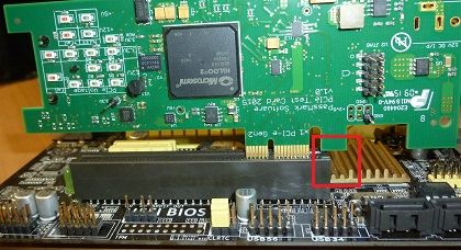
Figure 1. Interference tab prevents insertion of PCIe cards into a PCI slot
What does a PCIe slot look like?
-
A PCIe slot looks similar to a PCI slot, however PCIe slots, compared to PCI slots, generally have a lower profile, a slightly different key spacing and are keyed on the opposite end. PCIe slots can range in length from x1 (1 lane) up to x32 (32 lanes). See Figure 2 for a side-by-side comparison of a x16 PCIe slot, a x1 PCIe slot and a PCI slot.
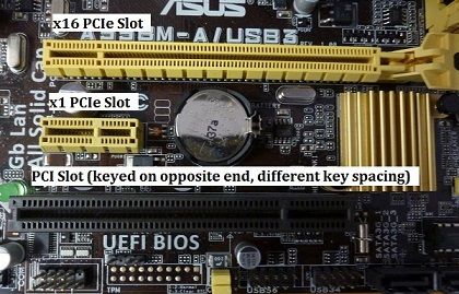
Figure 2. PCIe and PCI slots
What PCIe slot lengths can the PCIe Test Card be used in?
- The PCIe Test Card has a x1 and x4 edge. The x1 edge can be inserted into any PCIe slot (x1 and up). The x4 edge can be inserted into any PCIe slot x4 and up. PCIe cards cannot be inserted into slots shorter than the length of it's edge connector.
What generation of PCIe protocol can the PCIe Test Card be used in?
- The PCIe Test Card can be tested in any generation of PCIe slot. The PCIe Test card operates at speeds up to gen2.0 (5Gbps per lane). The capabilities of a PCIe link depend on the highest speed capabilities that both the endpoint and the host can agree on. If the PCIe Test Card is inserted in a gen2.0 slot, it will perform at gen2.0. If it is inserted in a gen3.0 slot, it will be limited by the card to performing at gen2.0. If it is inserted in a gen1.0 slot, it will be limited by the slot to performing at gen1.0.
Which operating systems are these cards compatible with?
- Windows 7, 8, 10, 11 and 2008 Server (in 32bit and 64bit).
- Linux is also supported.
Do I need a device driver to use these cards?
- A device driver is required for Windows and Linux. It is supplied with the cards on a mini-CD or it can be downloaded. Windows will prompt for the device driver the first time a card is used. The installation process is covered in the install guide.
Are the device drivers compatible with all versions of BurnInTest and PCIeTest?
- PCIeTest and the BurninTest Professional v8.1.1000 onwards work with any version of the PCIe Test device driver, however it is recommended that the latest version be used.
Does the PassMark PCIe Test card appear in my Device Manager as a new PCIe Device?
- Yes, you can see the devices in the Windows device manager. They appear with the label, "PassMark PCIe Test card".
What should I do if PCIe Test card doesn't appear in my Device Manager?
-
- Make sure the PCIe Test Card is properly inserted into the PCIe slot (see figure 1).
- Check to see PCIe voltages are present (B1, B2, B3, A2, A3, B8, A9 , A10, 3.3V AUX LEDs should be on).
- Some BIOS implementation allow enabling of a power management protocol named Active State Power Management(ASPM) which sends the card into low power mode before loading the operating system. Make sure Active State Power Management is disabled in BIOS.
What is the meaning of the 24 LEDs on the device Top Side / Bottom Side
-
- Top Side
- Green LEDs for each 12V pin (5)
- Red LED = 12V out of spec'd range
- Green LEDs for each 3.3V pin (3)
- Red LED = 3.3V out of spec'd range
- Green LED for 3.3V aux rail
- Green LED for 12V PSU rail (from Molex/SATA connector)
- Red LED = 12V out of spec'd range
- Green LED for 5V PSU rail (from Molex/SATA connector)
- Red LED = 5V out of spec'd range
-
- Bottom Side
- Yellow LED = TX Activity
- Green LED = RX Activity
- Red LED = I/O Error
- Orange LED = Sleep
- Green LED = PCIe Gen2/3
- Yellow LED = Misc
- Green LED = Loopback Mode
- Yellow LED = Benchmark Mode
- Orange LED = Oscilloscope Mode
What is the acceptable range of the measured voltage rails?
-
The acceptable range of the various voltages measured by the PCIe Test Card are based on the ranges specified in the PCIe Electromechanical and ATX Power Supply Specifications.
Measured Rail/Temp Minimum Maximum 12V PCIe 11.04V 12.96V 12V PSU 11.40V 12.60V 5V PSU 4.75V 5.25V +3.3V PCIe or 3.3Vaux 3.003V 3.60V
Why are there so many LEDs on the PCIe Test Card dedicated to indicating 12V and 3.3V power?
-
Each power-indicator LED corresponds to a power pin on the PCIe edge connector. Each PCIe connector and PCIe card therefore has five +12V, three +3.3V and one 3.3Vaux contacts/pins, respectively. (Multiple pins per power rail facilitate a higher current capacity (1.1A per pin) in order to meet PCIe power delivery requirements.) Dedicated power-pin LEDs help to indicate whether any pins in the connector are failing to make contact or not supplying additional current.

Figure 3. Power Supply Pins on PCIe Edge Connectors
What power rails are used in PCIe?
- PCIe slots are required to provide two power rails: +12V and +3.3V. An optional 3.3Vaux rail is often also present.
What is the 3.3Vaux rail for?
- The 3.3Vaux rail is an optional power rail intended to supply low speed auxiliary signals such as the optional WAKE# signal.
How can you tell if the measured voltages fall within the acceptable range?
-
Out-of-spec voltage measurements are indicated to the user in four different ways.
- The red 'voltage fail' LEDs located top-side of the PCIe Test Card light up automatically if the 12V PCIe, 3.3V PCIe, 12V Molex or 5V Molex voltage rails are found to fall out of the specified range (see table above). No communication with the driver or PCIeTest.exe application is needed in this usage scenario.
- For more detailed voltage data, the PCIeTest.exe application can track the measured minimum and maximum voltages of all inputs, including 3.3Vaux and temperature, even during benchmark and loopback tests.
- You can measure the 12V and 3.3V PCIe power rails directly using an external voltage measuring tool such as a multimeter or an oscilloscope. The power rails can be probed by connecting the tool's measurement terminals to the labeled jumper headers (+12V, +3.3V, and GND) on the PCIe Test Card.
- And finally, the user can monitor up to two voltage rails or temperature in real-time using PCIeTest.exe in 'voltage mode'. A green band is imposed over the output graph to indicate whether the measured voltage falls within the acceptable range. 'Voltage mode' keeps track of the number of out-of-range spikes detected.
What do transients or spikes on the power rails look like?
-
Transients due to electrical noise generally appears as sharp peaks or dips deviating from a more or less constant measured voltage. See the below figure for an example of the PCIe Test Card in 'voltage mode' detecting noise on the system power supply's 5V line.

The 12V and 5V DC rails measured directly from the ATX power supply are more likely to exhibit high frequency noise as DC rails supplied to the motherboard and subsequently to the PCIe slot are generally decoupled from noise at an early stage.
Can I run multiple copies of PCIeTest at the same time?
- Yes you can run multiple instances of the PCIeTest application at the same time, however you need to make sure you have opened and configured them all them all to be using the correct PCIe cards before you start the first test.
Can I run multiple cards at the same time?
- Yes.
Does the Molex/SATA power always have to be connected?
- No. The Molex/SATA power only needs to be connected if you wish to measure the +12V and +5V PSU rails. When not connected, you can expect the red 'Power Fail' and green 'Power' LEDs corresponding to these rails to be lit up and off, respectively.
Can I run PCIeTest at the same time as BurnInTest?
- No, only one of these programs should be run when testing the PCIe Test Cards.
Is the PCIe Test Card hot-pluggable?
- Due to a lack of motherboards that support PCIe hot-plugging (hot-insertion and removal), the PCIe Test Card was not developed to support hot-plugging.
What type of PCIe data transfer type does the PCIe Test card use?
- When running on BurnInTest or PCIeTest, packet DMA transfers are used.
The red Error LED goes on. What does this mean?
- It means a DMA transfer has not been completed successfully and has timed out.
What maximum speed should I expect from my PCIe slot?
-
PCIe Gen2.0 is normally quoted as 5Gbps per lane. Data rates will never reach these speeds on a real device because some signaling bandwidth is used by 8b/10b bit encoding, TLP, DLLP and PLP overhead. On a correctly functioning PC with a single PCIe device connected, you should typically see measured maximum speed results in the order of approximately:
Generation Link Width Speed 1.0 x1 220 MBps 1.0 x2 420 MBps 1.0 x4 850 MBps 2.0 x1 420 MBps 2.0 x2 850 MBps 2.0 x4 1200* MBps *The PCIe Test Card has a maximum bandwidth of 1325 MBps, so the card cannot benchmark up to the PCIe Gen 2.0 maximum theoretical x4 bandwidth of ~1850 MBps.
Is there an Application Programming Interface available?
- An API will be available at some point in the future. Please contact us for more information.
Is the firmware on the PCIe Test Card upgradeable?
- Yes, however you will need Microsemi's FlashPro4 JTAG programmer to do it yourself, otherwise your PCIe Test Card can be posted back to us for upgrade.
Does PCIe Test card detect low-level errors in communication?
-
Yes, When running loopback test, PCIe Test application reports following low-level errors:
Name of Error Classification & severity Layer Detected Receiver Error Correctable Physical Bad TLP Correctable Link Bad DLLP Correctable Link Replay Time-out Correctable Link Replay Number Rollover Correctable Link Poisoned TLP Received Uncorrectable - Non Fatal Transaction ECRC Check Failed Uncorrectable - Non Fatal Transaction Unsupported Request Uncorrectable - Non Fatal Transaction Completion Time-out Uncorrectable - Non Fatal Transaction Completion Abort Uncorrectable - Non Fatal Transaction Unexpected Completion Uncorrectable - Non Fatal Transaction Training Error Uncorrectable - Fatal Physical DLL Protocol Error Uncorrectable - Fatal Link Receiver Overflow Uncorrectable - Fatal Transaction Flow Control Protocol Error Uncorrectable - Fatal Transaction Malformed TLP Uncorrectable - Fatal Transaction Based on severity, PCIe errors reported by application are categorized as below:
Correctable: errors which may have an impact on performance (like latency, bandwidth), but no data/information is lost and PCIe link remains reliable. Such errors are corrected by hardware and no software intervention is required.Uncorrectable Non-fatal: errors which don’t have impact on the PCI link, but data/information is lost. Non-fatal errors are corrupted transactions that can’t be corrected. However, the PCI Test card continues to function correctly and other transactions are unaffected, only particular transaction is affected.Uncorrectable fatal: errors which have impact on PCIe link i.e. PCIe link is no more reliable and data/information is lost.